Phasor diagram voltage Phasor diagram Voltage regulators distribution power feeder control end used lines
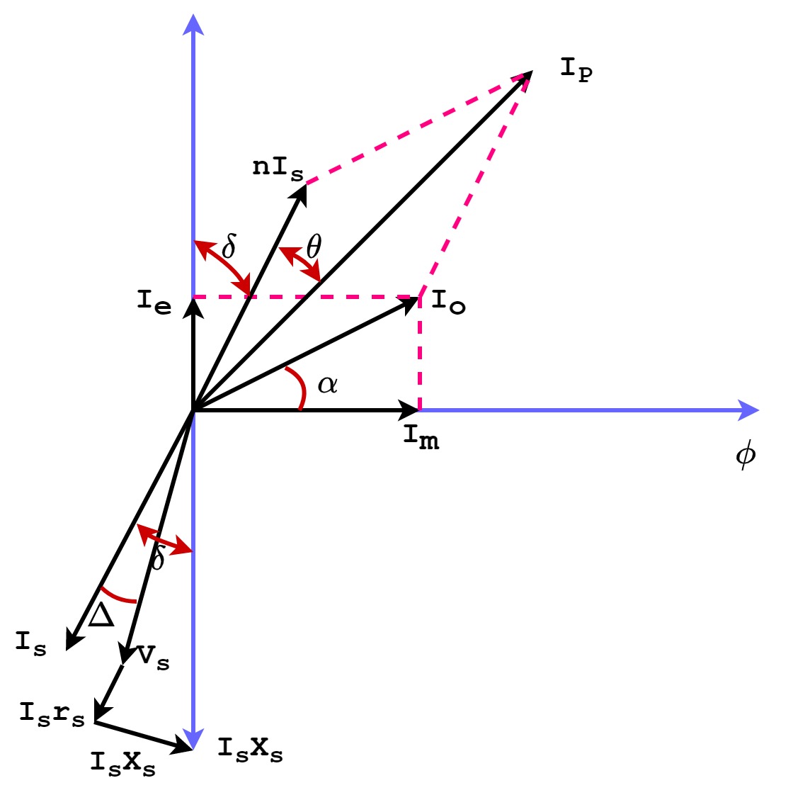
What is Current Transformer (CT)? Definition, Construction, Phasor
What is current transformer (ct)? definition, construction, phasor Phasor diagram ac voltage current representation diagrams gif vector represent rotating Double subscript notation in single phase system
Solved draw the phasor diagram representing the voltage and
Phasor sinusoidal sine rotating circuits voltage waveform phasors representation waveforms sinus algebra alternating domain equations ws frequency angular onda phasesPhasor reactance capacitive inductive imaginary diagram why resistance axis real component stack Phasor transformer current diagram ct circuit errors construction phasePhasor rl inductor explaination difference begingroup.
Phasor voltage current ac diagram circuit rlc power series phase length equation compressor calculate jq reactive write real angle laggingPhasor diagram of voltage and current of system shown in figure 7 in Voltage phasorPhasor voltages.

Alternating current circuits chapter 33 continued phasor diagrams
9.17. draw and explain phasor diagram for voltageand current in aThree phase star connection (y): three phase power,voltage,current What is the physical significance of phasor diagram why we use itIn a rlc series circuit, the phasor diagram below shows current and.
Current find phasors phasor solved transcribed text showCapacitor phasor diagram Phasor rlc voltage resulting phasors xc homeworklib calor golpeVoltage regulators used to control the voltage at the end of a.

Solved 3. figure 1 depicts the phasor diagram of three phase
Voltage phasor balanced winding transformer zigzag equivalent inductionWhy is the inductive reactance or capacitive reactance phasor on the Solved consider the following phasor diagram for voltages.Voltage and current phasor relationships for circuit elements.
Solved find the phasors for the current and for the voltagesBalanced three phase circuits voltage and current calculation Rlc series network: impedance, current, power factor, phasor diagramVoltage-current phasor diagram of a synchronous generator..

Phasor diagram of line side voltage and current with balanced
The phasor diagram of voltage (1) and current (2) rearranged in anPhasor circuits alternating continued Phasor voltage transformer apkPhasor synchronous.
Current transformer diagram phasor ct voltage secondary induced circuit circuitglobeSolved: choose the phasor diagram below that displays the How to draw phasor diagram at how to drawPhasor notation fig subscript corresponding electricalacademia.

Phasor diagram of voltages and current of the system shown in fig. 5
Phasor voltagesHow to draw phasor diagram at how to draw Phasor resistor circuitPhase phasor diagram line star connection voltages voltage three current power showing wye electrical electric fig.
Three phase voltage phasor diagramSolved depicts phasor problem Phasor diagram of voltage and current of system shown in figure 4 inPhasor voltage current.

Phasor circuit inductor developing
Phasor diagram choose displays below voltage drops relationship possible resistor between across solved vr transcribed text showPhasor diagram of line side voltage and current with balanced Voltage and current phasor relationships for circuit elementsPhasor rearranged orthogonal.
Phasor diagram of voltages and current of system shown in figure 2Phasor calculation circuits denotation having Phasor voltage phase balanced supplyPhasor voltage diagram current draw chegg representing transcribed text show.

Phasor ise
Inductive waveform phasor purely explainCurrent transformer .
.

Current Transformer - Construction, Phasor and Errors - Electrical Volt

Solved Find the phasors for the current and for the voltages | Chegg.com

Solved 3. Figure 1 depicts the phasor diagram of three phase | Chegg.com

Phasor diagram of voltage and current of system shown in Figure 4 in

In a RLC series circuit, the phasor diagram below shows current and