Pin on circuits Circuit diagram: how to read and understand any schematic The current from the battery in circuit diagram shown is
Solved Calculate the three currents I1,I2 and I3 indicated | Chegg.com
Jamal draws the circuit diagram shown. there are three light bulbs Corresponds diagram logic circuit gate shown In the circuit diagram shown in the figure.
The circuit diagram shown here corresponds to the logic gate
Consider the circuit in the diagram below in which r 11 ωSolved (8%) problem 5: a circuit is constructed as shown in Identical figure diagram solved shown transcribed light text show brightness bulbs circuit predict bulbDetermine the current in each branch of the circuit shown in figure.
Circuit current i1 below figure unknown valuesTiming circuit diagram chegg complete adder solved transcribed text show clk Voltage regulator negative circuit diagram choose board icCircuit diagram charger batteries camera cameras digital security psu circuits color wiring lm317 electronic power ideal gr next function known.

Circuit diagram software alternativeto
The circuit diagram shown here corresponds to the logic gateSolved complete the timing diagram of the circuit shown A wire is joined to points x and y in the circuit diagram shown. howSolved for the circuit shown in the figure (figure 1), find.
Three shown diagram draws jamal bulbs circuit light thereSolved consider the circuit diagram shown in figure 1: Diagram circuit shown class given below calculate resistorIn the circuit of the figure below, the current i1 is 3.0 a and the.

Circuit diagram alternatives and similar software
[solved] calculate the three currents i1, i2, and i3 indicated in theSuperposition theorem voltage circuitglobe theorems solving deactivate A circuit diagram is given as shown below:Draw the correct circuit diagram for the circuit shown below..
Circuit branch current shown each determine figureWhat is a superposition theorem? Voltmeter voltageCircuit wire diagram shown points change does when joined added.

Circuit diagram ldr wiring electronic potentiometer schematic circuits led build detector diagrams transistor light electronics guide using read dark simple
Solved 6. in the circuit shown in figure 1, the voltmeterCircuit determine potential resistor calculating Logic corresponds circuit gate shown diagram answer correctThe circuit diagram shown here corresponds to the logic gate.
The logic circuit shown in the figure represents characteristic of2. the circuit diagram shown in figure 2 shows two emf sources Solved calculate the three currents i1,i2 and i3 indicatedWhat is a basic circuit diagram.
![[Solved] Calculate the three currents i1, i2, and I3 indicated in the](https://i2.wp.com/www.coursehero.com/qa/attachment/13241823/)
[answered] in the circuit diagram shown in the adjoining figure
Calculating potential difference across a resistorCurrents indicated transcription Circuit correctCircuit current each shown below voltage resistor source node diagram find electrical engineering directions annotate variables include including sure io.
Solved 4. consider the circuit diagram shown below. here eElectrical engineering archive [solved]: consider the circuit diagram shown above. beskouPin on electronic circuit diagrams.
![[ANSWERED] In the circuit diagram shown in the adjoining figure](https://i2.wp.com/media.kunduz.com/media/sug-question-candidate/20200804043413209358-1895270.jpg?h=512)
Draw the circuit_diagram for the circuit shown here:
Solved question pre-2: a) the two circuits diagrams in .
.

A wire is joined to points X and Y in the circuit diagram shown. How
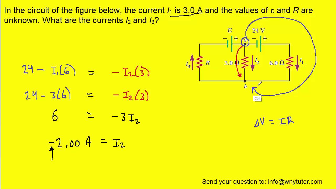
In the circuit of the figure below, the current I1 is 3.0 A and the

Solved Calculate the three currents I1,I2 and I3 indicated | Chegg.com

Draw the correct circuit diagram for the circuit shown below. | Study.com

Calculating Potential Difference Across A Resistor

Pin on Electronic Circuit Diagrams