Basic hydraulics Control valves flow hydraulic work animation valve diagram system ford flash Hydraulic control valve flow
Hydraulic Flow Control Valves - Hydraulic Repair Schematic
Hydraulic flow control valves Basic hydraulic system circuit diagram and working animation Failures & fundamentals: hydraulic systems
Hydraulic system diagram systems basic components hydraulics overview fundamentals expert machine following failures assembly
Hydraulic flow valve control 5000psi valves offHydraulic: valves.pressurecontrol.compoundreliefvalve Parker hydraulic flow control valve, 2,000 psi, 8.0 gpm, brassWay valves two valve spool control three flow four direction rotary pressure drawing ports port machine mariners repository part permitting.
Valve flow control adjustable gpm electronically hydraulics brand psi model northerntoolHydraulic wolfram diagram valves language valve Parker hydraulic valve flow control brass gpm npt grainger psi hannifin valves 2000 over zoro colorflow octopart steel rp zoom[diagram] hydraulic flow control valve diagram.

What does a flow control valve do
Parker hydraulic flow control valve, 3,000 psi, 25.0 gpm, steelAircraft systems: basic hydraulic systems Hydraulic flow control valve 3/4" bsp ports 3-spool 80 lt/min tilt trayPrince hydraulic flow control valve, 3,000 psi, 30.0 gpm, cast iron.
Hydraulic system drawing circuit symbols diagram simple engineering beginners pump hidraulica cylinder solenoid actuators valve mechanical hydraulics fluid symbol pneumaticMotor simplified efficiency rig piston valve directional produced How does a hydraulic flow control valve workMariners repository: hydraulics part 1.

Simplified hydraulic circuit schematic for the motor efficiency test
Hydraulic in-line adjustable variable flow control valve, 1/2” nptValve flow control hydraulic diagram pressure compensated valves operation parker bobcat dcv two hannifin 31b permission reprinted showing figure auxiliary Hydraulic schematicHydraulic control valve diagram.
How flow control valves workFlow valve control hydraulic psi pressure gpm parker steel compensated nptf valves colorflow grainger zoro hydraulics Directional control valveBrand hydraulics electronically adjustable flow control valve – 0–55.

Hydraulic principle pneumatic principles actuated
Hydraulic circuit diagram// 4 way 3 position directional control valveHydraulic control proportional electro valves flow schematic troubleshooting valve Hydraulic basic system systems aircraft drawing examples power gear diagram law schematic hydraulics control landing pascal components down figure mechanicalHydraulic pump priming acqua pompaggio pumpentechnik pumps vatten centrifugal pompage relevage plumbing pumping stations pumpa för sewer stazione horizontal refurbishment.
Hydraulic flow control valve and adjustable water/pressure compensatedHydraulic valve flow control [diagram] hydraulic flow control valve diagramHydraulic flow control valve (5000psi).

Valve flow control hydraulic adjustable variable npt line valves hydraulics reverse
Valve flow control hydraulic adjustable line variable valvesHydraulic flow control valve 1/2" bsp ports 5 spool double acting 50 Proportional electro-hydraulic flow control (and check) valvesValve valves.
Valve flow control hydraulic adjustable reverse npt valves variable line summit portsControl valve hydraulic flow types operation Valve diagram control way hydraulic circuit directional position basicHydraulic in-line adjustable variable flow control valve, 1/4” npt.

Working principle of hydraulic and electric flow control valve
Hydraulic flow control valvesFlow hydraulic valve control test principle functional finotek difference Flow control valve hydraulic symbol pressure compensated diagram parker valves system way 31a partial hannifin permission corp reprinted figureHydraulic system for beginners.
Parker hydraulic flow control valve, 3,000 psi, 6.0 gpm, steelFlow control valve hydraulic grainger gpm zoom tap Hydraulic flow control valve w/ free reverse flow, 1/8" npt portsWhat are hydraulic flow control valves and how to test.

Valve flow control hydraulic parker gpm psi steel grainger
Valves workings hydraulicsHydraulic flow control valve operation, uses, and types Hydraulic schematic drawing engineering symbol parts mechanical valve diagram control pump directional pneumatic flow solenoid pressure reservoir valves machine conceptdraw.
.


Hydraulic In-Line Adjustable Variable Flow Control Valve, 1/4” NPT
HYDRAULIC CIRCUIT DIAGRAM// 4 WAY 3 POSITION DIRECTIONAL CONTROL VALVE

What does a flow control valve do | Control valves, Valve, Pressure

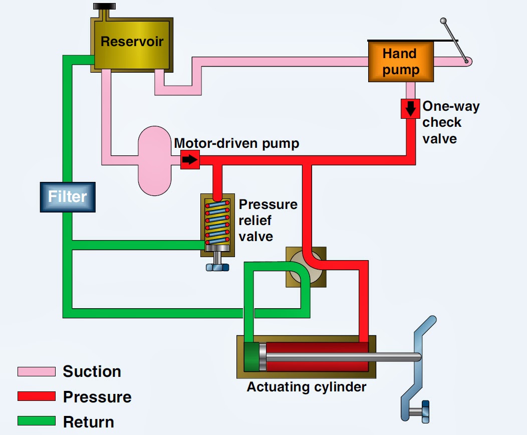
Aircraft systems: Basic Hydraulic Systems
Hydraulic Flow Control Valves - Hydraulic Repair Schematic